
|
|
|
Главная страница Систематические методы минимизации [0] [1] [2] [3] [4] [5] [6] [7] [8] [9] [10] [11] [12] [13] [14] [15] [16] [17] [18] [19] [20] [21] [22] [23] [24] [25] [26] [27] [28] [29] [30] [31] [32] [33] [34] [35] [36] [37] [38] [39] [40] [41] [42] [43] [44] [45] [46] [47] [48] [49] [50] [51] [52] [53] [54] [55] [56] [57] [58] [59] [60] [61] [62] [63] [64] [65] [66] [67] [68] [69] [70] [71] [72] [73] [74] [75] [76] [77] [78] [79] [80] [81] [82] [83] [84] [85] [86] [87] [88] [89] [90] [91] [92] [93] [94] [95] [96] [97] [98] [99] [100] [101] [102] [103] [104] [105] [106] [107] [108] [109] [110] [111] [112] [113] [114] [115] [116] [117] [118] [119] [120] [121] [122] [123] [124] [125] [126] [ 127 ] [128] ма используется для возбуждения линии в системах, показанных на рис. 7.102б,в,г, то разветвление может быть больше без ухудшения параметров передаваемых сипналов. Однако при одинаковом разветвлении и использовании линии с характеристическим сопротивлением Zo=37,5 Ом, имеющей в конце сопротивление 37,5 Ом (два включенных параллельно- интепральных резистора с сопро- 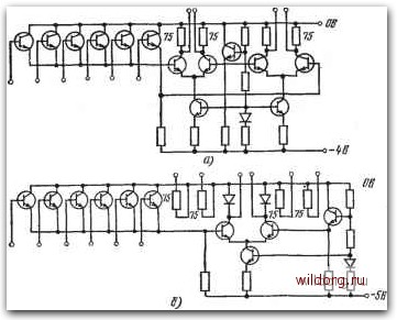 Рис. 7.103. а) схема ЭСЛ с двумя парами электрически изолированных выходов; б) схема ЭСЛ с отдельными согласующими сопротивлениями тивлением 75 Ом на выходе схемы), значительно улучшатся передний фронт и спад сигнала. Схема разработана, прежде всего, для возбуждения линий с характеристическим сопротивлением Zo=75 Ом и длиной до 70 см, с согласованием в начале и конце линии со- 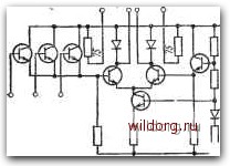 противлениям,и 75 ОлМ. Неиспользуемый выход должен быть через резистор с сопротивлением 75 Ом подключен на землю. Схема на рис. 7.104 предназначена для коротких соединений, до 8 см. В одном корпусе размещены две схемы. Соединяя выходы одинаковых схем, получае.м дополнительную логическую функцию. Интегральные резисторы 75 Ом соединяются с соответствующими выходами только у одной схемы, у остальных схем они не включаются. Недостатком является .изменение задержки в зависимости от числа одновременно переключаемых схем. При одновременно.м включении 1 ->4 схем разница задержек составляет около 0,4 не и может .иметь большое значение с точки зрения режима работы всей системы. У схем типа FKH131 выходы обеих схем соединены прямо в корпусе. Рис. 7.104. Схема ЭСЛ, предназначенная для коротких линий - до 8 см Список литературы 1. Ghandi S. К., Thiel F. L. Pulse noise immunity in saturated logic eates «1ЕЕЕ Journal for solid-state circuits*, 1967, N 3, p. 81-86. 2. Hill C. F. Definitions of noise margin in logic systems. - «MuIlard Technical Communications*, 1967, N 9, p. 239-245. 3. Pierce W. H., Wilcox R. H., Mann W. C. Redundancy techniques for computing systems. Washington, Spartan Book Inc., 1962. 4. Davies A. C. The design of feedback shift registers and other synchronous counters. - «The Radio and Electronic Engineer*, 1969, N 5, p. 213-223. 5. Dean K. J. The design of parallel counters using the map method. -«The Radio and Electronic Engineer*, 1966, N 9, p. 1159. 6. Dean K. J. Conversion between binary code and some binary-decimal codes.- «The Radio and Electronic Engineer*, 1968, N I, p. 49-53. 7. Ettinger M. A., Jacob G. W. An algorithm for sequential circuit design.- «Computer Design*, 1968, N 5, p. 46-53. 8. Ettinger M. A. The synthesis of sequential circuits. - «Computer Design*,. 1968, N 12, p. 46-53. 9. Goode G. E. Novel approach to sequential design. - «EDN*, 1968, N 12, p. 50-62. 10. Graphic symbols for logic design. MIL-STD-806B. 11. Humprey W. S. Switching circuits. New York, McGraw-Hill Book Co., 1958. 12. Jakubajtis E. A. Asynchonni logicke obvody. Praha, Academia, 1968. 13. Karnaugh M. The map method for synthesis of combinational logic circuits.- «Commun. Electronics*, il.953, N 11, p. 539. 14. Klir J., Seidl L. K. Synteza logickych obvodu. Praha, SNTL, 1966. 15. Lagemann K. Die verschiedenen Flipflopparten und ihre Beschreibung durch Symbole und Wahrheitstabellen. - <<Valvo Berichte*, 1967, N 5, p. 149-188. 16. Lewin D. W. A new approach to the design of assynchronous logic. - «The Radio and Electronic Engineer*, 1968, N 12, p. 327-334. 17. Linford J. ROM at the top. -«The Electronic Engineer*, 1969, N 5, p. 64-71. 18. Traczyk W. Projektowanie tranzystorowych ukladow przelaczajacych. Warsza-wa, Wydawnictwa naukowo techniczne, 1966. 19. Wickers W. E. Logic design with integrated circuits. New York, J. Willey, 1968. 20. Armstrong D. R. TTL interfacing with GRL 1/1,1 and GRL 101. -«Mullard Technical Communications*, 1970, N 106, p. 130-138. 21. Mc Cann M. R. High performance monostable and astable circuits using DTL and TTL gates. - «Microelectronics», 1969, N. 11, p. 30-34. 22. Growther G. C, Deli G. C. ECL nanosecond logic system: Design considerations for elements and interconnections. - «Mullard technical Communications*, 1967, N 87, p. 150-179. 23. Deerson J. FC Family of DTL integrated circuits. Eindhoven, Philips, 11970. 24. FL 100-Siemens-DigitaIbausteine in integrierter Technik. Technische Mitteilun-gen 2-6300-126, 2-6300-127. Siemens AG. 25. Gascoigne R. M. Some properties of fast current steered logic. - «Microelect-ronics*, 1969, N 4, p. 30-35. 26. Chest R. C. TTL integrated circuits: High speed considerations. SGS, 1968„ N AR 183. 27. H lOO-Storsichere Logikschaltungen. Отчет ARD 12. SGS Deutschland G. m. b. H. 28. Integrated diode matrices. Radiation Inc., 11.967 October. 29. Kruger A. Circuits integres de logique: La Logique ECL a mode non satu-re. - «Electronique Industrielle*, 1968, N 3, p. 117-123. 30. Kruger A. Line driving with 1С s. - «Microelectronics*, 1968, N 7, p. 34-37. 31. Lejeune A. La famille MECL III. -«Electronique Industrielle*. 1969, N 3» p. 145-149. 32. Maillet J. C. Etude dfes reflections sur les circuits TTL utilises avec des lignes de transmission.-«Electronique Industrielle*, 1968, :N 114, p. 427-432. 33. Mairet М. Une nouvelle famille logique TTL: La serie SN 54S/74S a diodes Schottky. - «Electronique industrielle», 1Ш70, N 9, p. 535-540. 34. Mullard TTL integrated circuits applications. London, Mullard Limited, 1970. 35. Murray D. E. Driving long lines with ICs. - «Microelectronics», 1969, N 5, p. 24-29. 36. Murray D. E. Driving long lines with ICs. - «Microelectronics», 1969, part. 2, N 6, p. 36-39. 37. Reflection phenomena when TTL gates are connected to long lines. Mullard Ltd, 1969, June. 38. Storsicherheit in Schaltungen mit FL 100 Digitalbausteinen. Technische Mit-teleilungen 2-6300-135. Siemens AG. 39. Tirrell J. C. Power considerations in high speed TTL logic. - «Computer De-sign», 1969, N 2, p. 36-47. [0] [1] [2] [3] [4] [5] [6] [7] [8] [9] [10] [11] [12] [13] [14] [15] [16] [17] [18] [19] [20] [21] [22] [23] [24] [25] [26] [27] [28] [29] [30] [31] [32] [33] [34] [35] [36] [37] [38] [39] [40] [41] [42] [43] [44] [45] [46] [47] [48] [49] [50] [51] [52] [53] [54] [55] [56] [57] [58] [59] [60] [61] [62] [63] [64] [65] [66] [67] [68] [69] [70] [71] [72] [73] [74] [75] [76] [77] [78] [79] [80] [81] [82] [83] [84] [85] [86] [87] [88] [89] [90] [91] [92] [93] [94] [95] [96] [97] [98] [99] [100] [101] [102] [103] [104] [105] [106] [107] [108] [109] [110] [111] [112] [113] [114] [115] [116] [117] [118] [119] [120] [121] [122] [123] [124] [125] [126] [ 127 ] [128] 0.0138 |